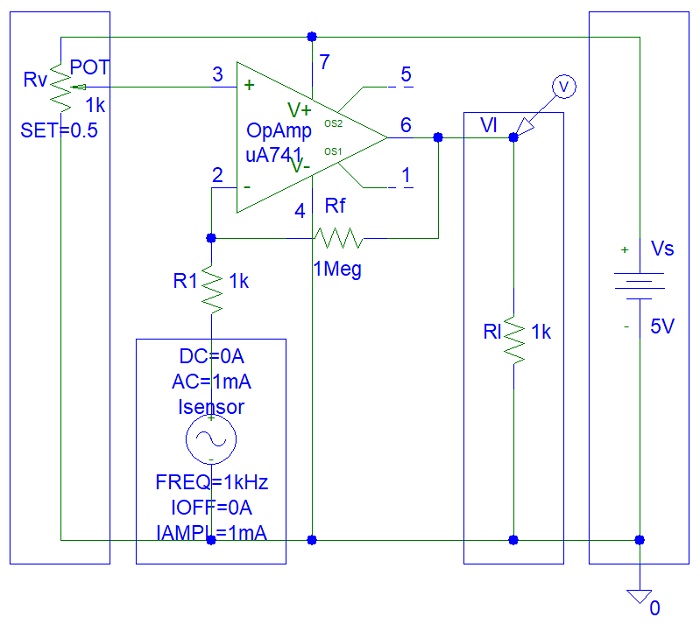
The circuit below is a bad op-amp sensor biasing.
When Rv is set to provide maximum voltage at pin 3 (5 V), the potential voltage across the sensor will be about the same value (probably 4.9 V). This value could be above the maximum potential voltage specified in the sensor datasheets and will thus burn and damage the sensor.
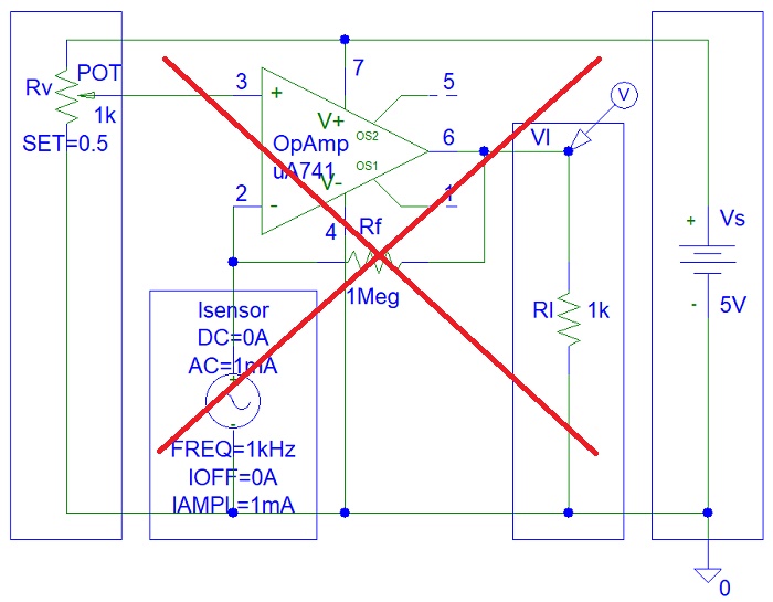
A modified circuit shows a sensor in series with R1 resistor. This R1 resistor will limit the maximum potential voltage across the sensor and will thus prevent sensor failure.